A.C
CIRCUIT
An A.C circuit is the closed path followed by alternating current.
When a sinusoidal alternating voltage is applied in a circuit, the resulting alternating current is also sinusoidal and has the same frequency as that of applied voltage.
However there is generally a phase difference between the applied voltage and the resulting current.
As we shall see, this phase difference is introduced due to the presence of inductance (L) and capacitance (C) in circuit.
While discussing A.C circuits our main points of interest are;
(i) Phase difference between the applied voltage and circuit current
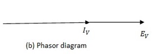
(ii) Phasor diagram. It is the diagram representation of the phase difference between the applied voltage and the result circuit current.
(iii) Wave diagram
(iv) Power consumed.
A.C CIRCUIT CONTAINING RESISTANCE ONLY
When an alternating voltage is applied across a pure resistance, then from electrons  current flow in one direction for the first half cycle of the supply and then flow in the opposite direction during the next half cycle, thus constitute alternate current in the circuit.
Consider a pure resistor of resistance R connected across an alternating source of 
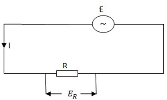
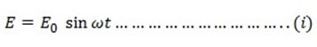
Suppose the instantaneous value of the alternating  is given by
If I is the circuit current at that instant, then by ohm’s law


The value of I will be maximum Io when

Therefore equation (ii) becomes
From 
Since sin  t = 1 then I = Io

1) Phase Angle
It is clear from equation (i) and (iii) the applied  and circuit current are in phase with each other
  they pass through their zero values at the same instant and attain their peak value both positive and negative peaks at the same instant.
This is indicated in the wave diagram shown in figure below.
The  diagram shown in figure below also reveals that current is in phase with the applied voltage.
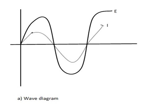
Hence in an a.c circuit, current through R is in phase with voltage across R.
This means that current in R varies in step with voltage across R. If voltage across R is maximum current in R is also maximum, if voltage across R is zero, current in R is also zero and so on.
2) Power Absorbed
In a.c circuit, voltage and current vary from instant to instant. Therefore power at any instant is equal to the product of voltage and current at that instant.
Instantaneous power P


Since power varies from instant to instant the average power over a complete cycle is to be considered.
This is found by integrating equation………..(iv) with respect to time for 1 cycle and dividing by the time of 1 cycle. The time per one cycle is T.
Average power P
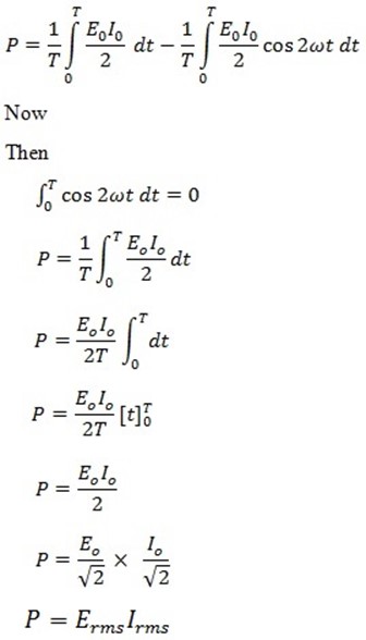
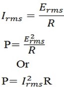
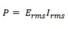
Therefore, average power absorbed by a resistor in an a.c circuit is equal to the product of virtual voltage ( Erms) across it and virtual current ( Irms) through it.
Obviously, this power is supplied by the source of alternating  .
.
Since
WORKED EXAMPLES
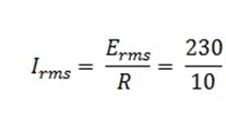
1. An a.c circuit consists of a pure resistance of 10Ω and is connected across an a.c supply of 230V, 50 Hz.
Calculate
i) Circuit current
ii) Power dissipated and
iii) Equations for voltage and current
Solution
Erms = 230V R = 10Ω f = 50HZ
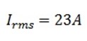
i) Circuit current
ii) Power dissipated P
= 230 x 23
∴ P = 5290 W
iii)Equations for voltage and current
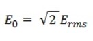
=  x 230
x 230
 = 325. 27V
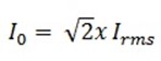
= 2 x 23
∴  = 32.52A
ω = 2
= 2
ω = 314
∴ The equations of voltage and current
E = 325.27 sin 314t and I = 3.52 sin 314t
2. In a pure resistive circuit, the instantaneous voltage and current are given
E = 250 sin 314t
I = 10 sin 314t
Determine
i) Peak power
ii) Average power
Solution
In a pure resistive circuit
i) Peak power = 
= 250 x 10
∴ Peak power = 2500W
ii) Average power P
P = 
P = 
∴
P = 1250 W
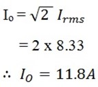
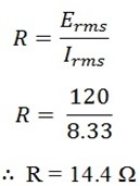
3. Calculate the resistance and peak current in a 1000 W hair dryer connected to 120V, 60Hz supply. What happens if it is connected to 240V line?
Solution
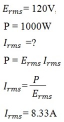
Peak current Io
Resistance of hair dryer R
When connected to 240V line, the average power delivered would be
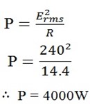
This would undoubtedly melt the heating element or the coils of the motor.
4. A voltage E = 60sin 314t is applied across a 20 Ω resistor. What will;
i) An a.c ammeter
ii) Ordinary moving coil ammeter in series with resistor read?
Solution
i) E = 60 sin 314t
An a.c ammeter will read the r.m.s value.
 =
= =
= 

Therefore a.c a meter will read 2.12A
ii) An ordinary moving coil ammeter will read average value of alternating current. Since the average value of a.c over one cycle is zero, this meter will record zero reading.
5. What is the peak value of an alternating current which produces three times the heat per second as a direct current of 2A in a resistor R?
Solution
Heat per second by 2A
 =
=  R
R
H =  R
R

 4R
4R
Three times heat per second
3
3 = 12R
= 12R
If Iv is the r .m .s value of the a.c heat per second in R

 R
R
12R =  R
R
 = 12
= 12


Peak value is given by, 

∴ Peak value = 24 = 4.9A
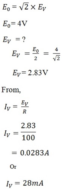
6. An a.c voltage of 4V peak (maximum) is connected to a 100Ω resistor R
a) What is the phase of the current and voltage?
b) Calculate the current in R in mA
c) What is the power in R in mW
Solution
a) The current and voltage are in phase
b) Current is R
c) Power in R
P =  R
R
P = 0.0282 x 100
P = 0.078W
P = 78mW