A.C CIRCUIT CONTAINING INDUCTANCE
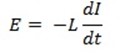
When alternating voltage is applied across a pure inductive coil a back  (E) is induced in the coil due to its self inductance.
E = – 
The negative sign indicates that induced e. m .f opposes the change in current.
In order to maintain the flow of current the applied voltage must be equal and opposite to induced voltage at every instant.
Consider a pure inductor of inductance L connected across an alternating source of 
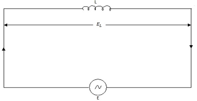
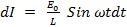
E = Eosin ωt
Suppose the instantaneous value of the alternating e. m. f is given by
E sin wt ………. (
 )
)
If I is the current in the circuit and  is the rate of change of current at that instant, then e. m. f induced in L is given by
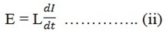
As applied voltage is equal and opposite to induce e .m .f at every instant
From, Equation
(i) and Equation (ii)

Integrating both sides we get
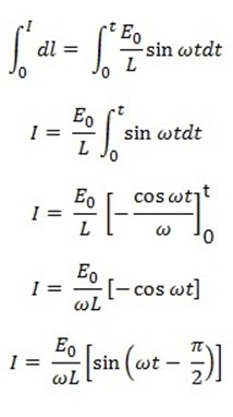
The value of I will be maximum Io when, Sin = 1
= 1
Then,

Substituting the value of =
=  in equation (iii)
I =  sin (wt –
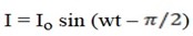 ……………….. (iv)
I) Phase Angle
It is clear from equation (i ) and (iv) that circuit current lags behind the applied voltage by ( /2) radians or 900.
This fact is also indicated in the wave diagram.
The phase diagram in figure below also reveals the fact that  lags behind
  by 90º
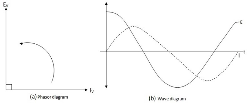
Hence in an a.c circuit current through L lags behind the voltage across L by 90º
This means that when voltage across L is zero, current through L is maximum and vice versa.
From
E = L
Now,  is maximum when circuit current is zero and
  is zero when circuit current is maximum.