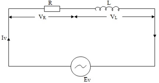
A.C CIRCUIT CONTAINING R AND L IN SERIES
Consider a resistor of resistance R ohms connected in series with pure inductor of L Henry.
Let
 = r.m.s value of applied alternating e.m.f
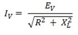
 =r.m.s value of the circuit current
VR =  R when VR is in phase with
VL = 
 where
where  leads
leads  by 90º
Taking current as the reference phasor, the phasor diagram of the circuit can be drawn as shown in figure.
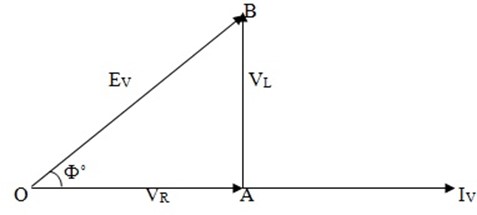
The voltage drop VR is in phases with current and is represented in magnitude and direction by the phase OA.
The voltage drop VL leads the current by 90º and is represented in magnitude and direction by the phase AB.
The applied voltage  is the phasor sums of these two voltage drops
 =
=  +
+ 
 =
= 
 =
= 
 =
= 
1) Phase Angle
It is clear from the phasor diagram that circuit current  lags behind the applied voltage
  by Φº.
Therefore we arrive at a very important conclusion that in an inductive circuit current lags behind the voltage.
NUMERICAL EXAMPLE
1. Three impedance are connected in series across a 200V, 50Hz supply. The first impedance is a 10┦ resistor and the second is a coil or 15 ┦ inductive reactance and 5 ┦ resistance while the third consists of a 15 ┦ resistor in series with a 25┦ capacitor
Calculate
i) Circuit current
ii) Circuit phase angle
iii) Circuit power factor
iv) Power consumed
Solution
i) Total circuit Resistance
R = 10 +5 + 15
R = 30 ┦
Total Circuit reactance
X = XL – XC
X = 15 – 25
X = -10 ┦ (capacitive)
Circuit impedance Z
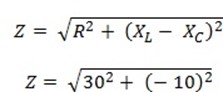
Z = 31. 6 ┦
Circuit current IV
IV = E v
Z
I V = 200
31.6
IV = 6. 33 A
ii) Circuit phase Angle
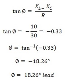
iii) Circuit power factor
Power factor = COS θ
= COS 18 .26º
Power factor = 0. 949
iv) Power consumed P
P = EV IV Cos ∅
P = (200 x 6.33) x 0. 949
P = 1201. 4 W
Alt
P = Iv2 R
2. A 230V, 50Hz supply is applied to a coil of 0.06 H inductance and 2.5 Ω resistance connected in series with 6.8 μF capacitor
Calculate
i. Circuit impedance
ii. Circuit current
iii. Phase angle between EV and Iv
iv. Power factor
v. Power consumed
Solution
i) Inductive reactance XL
XL = 2ΠfL
XL = 2Πx 50 x 0.60
XL = 18 .85 Ω
Capacitive reactance XC
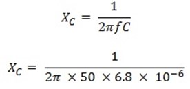
XC = 468 Ω
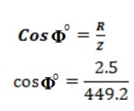
Circuit Impedance
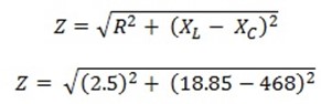
Z = 449. 2 Ω
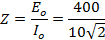
ii) Circuit current IV


IV = 0.152 A
iii) Phase angle between EV and IV
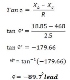
iv) Power factor
Cos Φ = 0.0056
v) Power consumed P
P = EVIS Cos Φ
P = 230.x 0.512 x 0.0056
P = 0.66 W
3. A resistance R, and inductance L = 0.01H and a capacitance C are connected in series. When an alternating voltage E = 400Sin (3000t- 200) is applied to the series combination, the current flowing is 10√2 Sin (3000t – 650). Find the value of R and C
Solution
The circuit current lags behind the applied voltage by θ
θ = 650 – 20
θ = 450
This implies that the circuit is inductive i.e.
XL > XC
The net circuit reactance X
X = XL –XC
Now
XL = ωL
XL = 3000 x 0.01
XL = 30 Ω
Also
From 


Circuit Impedance Z
Z = 28.3 Ω
Now
Z2 = R2 + X2
Z = R2 + R2
Z2 = 2R2
Z = R √2

R = 20Ω
Now
X = XL – XC
20 = 30 – XC
XC= 10Ω
From
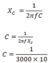
C = 33.3 x 10 -6 F
4. A series RLC circuit is connected to an a.c (220V, 50 H) as shown in the figure below
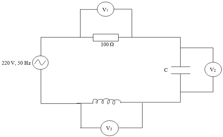
If the reading of the three volt meter V1 V 2 and V3 are 65V, 415V and 204V respectively.
Calculate
i. The current in the circuit
ii. The value of inductor L
iii. The value of capacitor C
Solution
Here voltmeters are considered ideal i.e. having infinite resistance.
Therefore, it is a series RLC circuit
i) Circuit current IV

IV = 0. 65 A
ii) Inductive reactance XL
XL = 318. 85 Ω
Inductance L
L = 1H
iii) Capacitive reactance XC
XC = 638. 46Ω
Capacitance C

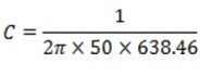
C = 5 x 10⁻⁶ F
5. A coil of resistance 8Ω and inductance 0.03H is connected to an a.c supply of 240V, 50 Hz.
Calculate
i) The current the power and power factor.
ii) The value of a capacitance which when connected in series with the above coil causes no change in the value of current and power taken from the supply
Solution
i) Reactance of the coil XL


XL=9.42 Ω
Impedance of the coil Z
Z = 12. 46 Ω
Circuit Current IV


IV = 19.42 A
Power consumed

P= (19.42)2 x 8
P= 3017 W
Power factor Cos Φ
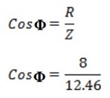
Cos Φ = 0.65 lag
ii) To maintain the same current and power, the impedance of the circuit should remain unchanged. Thus the value of capacitance in the series circuit should be such so as to cause the current to lead by the same angles as it previously lagged.
This can be achieved if the series capacitor has a capacitive reactance equal to twice the inductive reactance.
XC = 2XL
XC = 2 x 9 .42
XC = 18.84 Φ
Now


C = 169 x 10-9 F