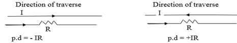
RULES FOR FINDING POTENTIAL DIFFERENCE(pd) IN A LOOP
If the resistance is traversed in the direction of the current,the chage in potential is -IR in the opposite direction is +IR
If a set of emf is traversed in the direction of emf the change in potential is +ve(+E) in the opposite direction it is(-E)
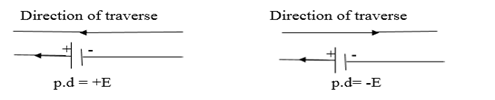
The choice of the direction of the traverse depend on yourself
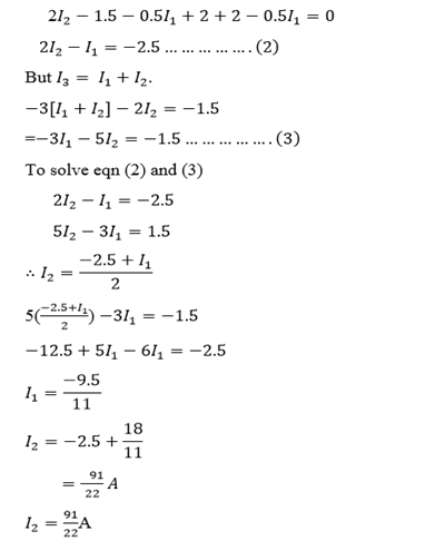
Solution

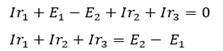
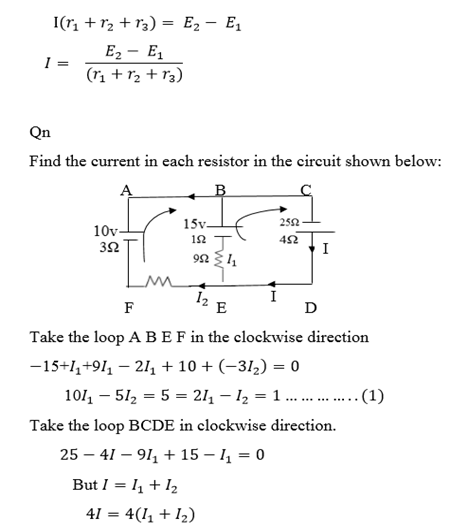
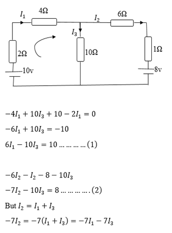
Applying Kirchhoff’s laws in the clockwise direction we have
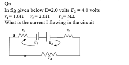
Qn.
Determine the magnitude of 
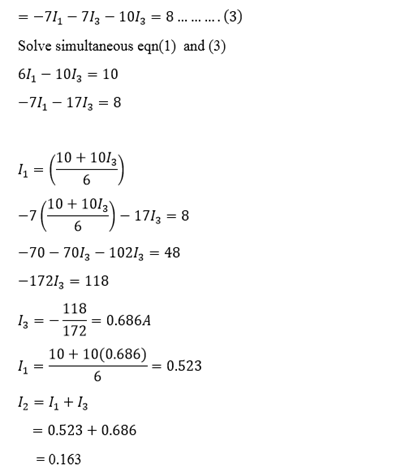
The minus sign tells that the current is in of the site direction (from the one assumed)
Qn.
On the basis of Kirchhoff’s laws determine the numerical values for the current
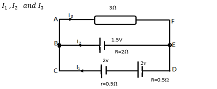
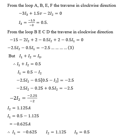
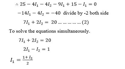
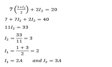
Take the loop B E D C in clockwise direction.
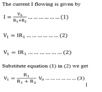
POTENTIAL DIVIDER
The resistance box in series are often used to provide known fraction of a given potential difference
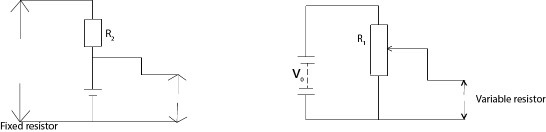
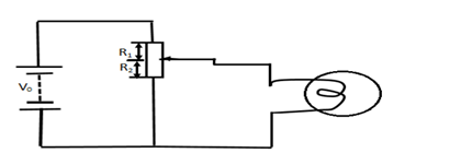
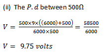
(iii) With load.
A resistor with a sliding contact can similarly be used as shown in figure (ii) to provide continuous variable potential difference from zero to a full supply by value V0.
This is a convenient way of controlling the voltage applied to a load such as lump. The resistor of the load R3 however acts in parallel with resistor R1 hence equation (1) is no longer true.
Qn.
What is the final potential difference between A and B in the direction circuit below (I) in the circuit as shown (II) if an additional 5000Ω resistor where connected from A to B
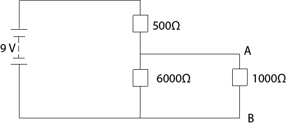
Solution
(i) Final p.d between 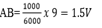
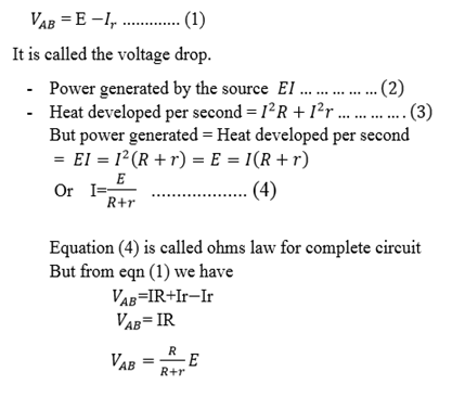
OHM’S LAW FOR COMPLETE CIRCUIT
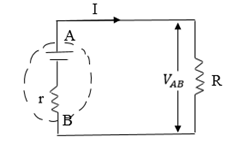
There exist certain device such as battery and electronic generators which are able to maintain a potential balance between two points to which they are attached to devices are called a set of electromotive force put the normally have some internal resistances. When the current flow through the battery setsup a p.d Ir across the internal resistance. The resistor of resistance R which is connected to the battery is called the load.
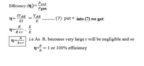
OUT PUT AND AN EFFICIENCY


power generated by the source the current
WHEATSTONE BRIDGE:
– Wheat stone bridge is a circuit that enable resistance to be measured accurately:
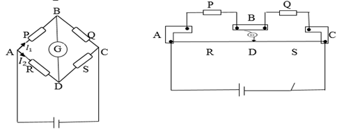
Four resistors P, Q , R and S are joined as shown in the figure above
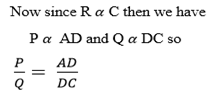
If P is the known resistor Q must be known as well as R and S or their ratio one or more of Q, R and S are adjusted until there is no deflection on G, the bridge is then said to be balanced.
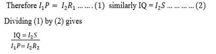
At balance point no current through G so p.d across BD=0 and p.d across AB=p.d across AD. Also current through R = current through Current through p=current through

Qn.
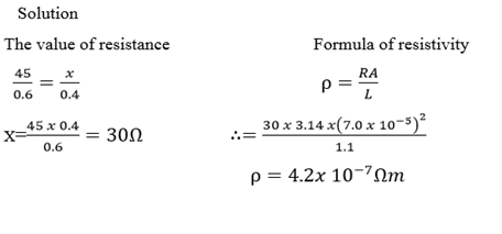
A wire of length 1.1 meter and Radius  is connected across the right gap of the metre bridge when a resistance of 45 Ω is introduced in the left gap from a resistance box connected across it. The balance point is obtained 0.6m from left side. Calculate the specific resistance (resistivity) of the material of the wire
Qn.
A  and
and  resistor are connected in series combination is connected across a 100v supply of negligible internal resistance as shown in the figure below:
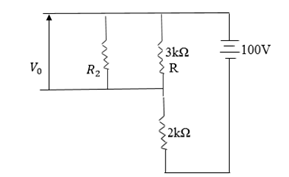
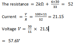
(i) What is the output voltage  of the load resistance
(ii) What current resistance through the load resistor  in (i) above.
I=21.15.
Solution