MAGNITUDES FOR CURRENT CARRYING CONDUCTORS
Laws of Biot and Savant.
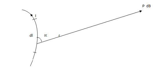
It state that the flux density dB= at point P due to a small element dl of a conductor carrying
Where r is the distance from the point P to the element is the angle formed it to P.
B: FLUX DENSITY = INDUCTION OR MAGNETIC INDUCTION
MAGNETIC FIELD
Equation (1) can be written as
dB=KIdlsinx
Where K is the constant of proportionality and it depends on the medium in which the
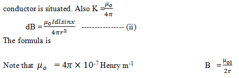
B AT THE CENTRE OF A NARROW CIRCULAR COIL
Suppose the coil is in air has a radius of r carries a steady current I and it is considered to consist of current element of length dl. Each element is at the distance r from the centre o and it is at the
Example
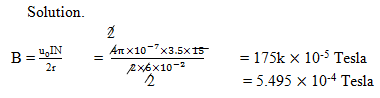
A coil of wire with 15 turns of radius 6.0cm, has a current of 3.5A flowing through it. What is the magnetic flux density at the center of the coil?
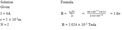
Example
What is the magnitude of the flux density produced the center of a coil of radius 5cm carrying current of 4A in air.
Example
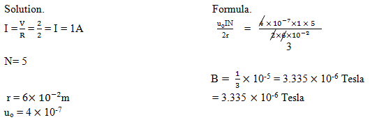
A circular coil of radius 6cm consisting of 5 turns carries a current supplied from 2v accumulator of negligible internal resistance. If the coil has a total resistance of 2┦. Calculate the magnetic field induced at the centre
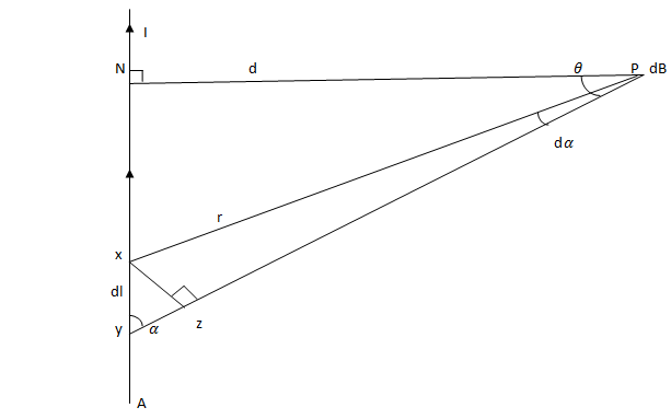
B DUE TO A LONG STRAIGHT WIRE AT A DISTANCE d SIDE THE WIRE
Consider a very long wire YN carrying a current I. Take P to be a point outside the wire but also this point is considered to be very near to this wire.
THE HALL EFFECT
Is the phenomenon where by e .m. f or voltage is set up transversely or across a current carrying conductor when a perpendicular magnetic field is applied
Consider a piece of conducting material in a magnetic field of flux density B
Suppose that the field is directed (perpendicularly) into the paper and that there is a current flowing from right to left.If the material is a metal the current is carried by electrons moving from left to right
Consider the situation of one of these electrons and suppose that it has a velocity V
The electron feels a force F which by Fleming’s left hand rule, is directed downwards .
Thus in addition to the electron flow from left to right electrons are urged away from face Y and towards face X. Anegative charged builds up on X, leaving a positive charged on Y so that a potential difference is established between X and Y. The buildup of charge continues until the potential difference becomes so large that it prevents any further increase . This maximum, potential difference is called the Hall voltage
Hall voltage
Is the potential difference created across a current carrying metal strip when the strip is placed in a magnetic field perpendicular to the current flow in the strip.
Actually, the magnetic field does not have to be totally perpendicular to the strip the magnetic field only needs to have a component that is perpendicular
The flow ceases when the e .m .f reaches a particular VH called Hall voltage
MAGNITUDE HALL VOLTAGE
Suppose VH is the magnitude of the Hall voltage and d is the width of the slab (the separation of x and y). Then the Electric field strength E set up across the slab is numerical equal to the potential gradient.
E = 
let Fv be the force exerted on an electron by the P.d between X and Y. Therefore when the buildup of charged on X and Y has ceased
F = Fv
BeV = eE
BV = E
BV= 
VH=BVd…………………..(i)
Where
E = The strength of the uniform electric field between X and Y due to the Hall voltage
VH = Hall voltage
d = The separation of X and Y
HALL VOLTAGE
Is the potential difference created across a current carrying metal strip when the strip is placed in a magnetic field perpendicular to the current flow in the strip
Actually the magnetic field does not have to be totally perpendicular to the strip the magnetic field only needs to have a component that is perpendicular
The flow ceases when the e .m. f reaches a particular value VH called Hall voltage. It has been shown that the current I in a material is given by I = neAV
Where
n = the number of electron per unit value
e = the charge on each electrons
v = the drift velocity of the electrons
A = the cross – sectional area of the material
V =  —————– (ii)
Sub equation (ii) into equation (i)
From
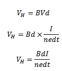
In figure A = d t and therefore
ELECTROMAGNETIC INDUCTION
An electric current create magnetic field, the reverse effects of producing electricity by magnetism was discovered by Faraday and is called electromagnetic induction
Induced  can be generated in two ways
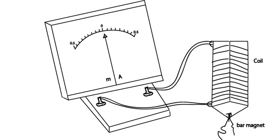
(a) By relative moment ( The generator effect )
if the bar magnet is moved in and out of a stationary galvanometer or small current is recorded during the motion but not at other time movement of the coil towards or away from the stationary magnet has the same results (figure above)
relative motion between the magnet and coil is necessary, the direction of the of induced current depends on the direction of the relative motion. And magnitude of current is produced increase with
i. the speed of the motion
ii. The number of turns in the coil
iii. The strength of the magnet used
(b) By changing a magnetic field (transformer effects)
In this case two coils are arranged one inside the other (Figure below) to galvanometer
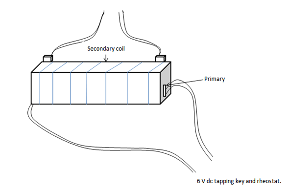
Rheostat the other called secondary is connected to galvanometer, switching the current on or off in the primary causes impulse of  and current to be induced in the secondary. Varying the primary current quietly altering the value of rheostat has the same effect.
Electromagnetic induction thus they occurs only when there is only change in primary current and also in magnetic fields it induces