AGRICULTURAL MECHANICS
Introduction: In order to do work ENERGY must e used, the rate of expenditure is proportional to the rate of doing work which is known as POWER.
Form of energy
I) Animated Energy: Is the energy of expended by using muscular power of human beings and animals. II) In animated Energy: Is the energy expended through transformation of natural resources e.g. fossil fuel, wind.
Definition: Is the application of engineering principles and techniques in agricultural sector involving utilization of all forms of energy through mechanical assistance in agricultural products.
Components: Tools, Implements, Machines.
Advantages of mechanization
i. Brings more intensive production
ii. Put more land into use
iii. Increases speed of work and capacity
iv. Releasing labour peak
v. Increases labour productivity. POWER
Limitation:
i. Not suitable in steep slopes e.g. mountain
ii. Need technical knowledge
iii. It is expensive.
iv. It is weather sensitive.
Definition: Is a proportional integration of the rate of energy expenditure and the rate of doing work.
TYPES OF POWER
I) Human power: Have the ability to work by using hands, operate machinery using legs and hands in daily agricultural activities.
When he uses hands in small scale and simple tools called hand tools. These include;
a) Hoe: This is a device used for turning the soil (digging), make ridges, uprooting stumps etc. It varies in weight, size and shape depending on the use.
b) Rake: A short spronged tool used in soil leveling, removing stones and weeds, breaking dumps during seed bed preparation.
c) Machete: A device used for lifting, inverting, leveling the soil, digging holes and even is used in transplanting seedlings.
d) Manure fork: A device whose sprongs have been spaced at regular intervals, similar to a spade but it has no plane blade used in spreading manure.
e) Hand craft: A boat shaped short blade tool used in digging hallow holes and in transplanting.
f) Mattock: Used in uprooting, digging and cutting.
g) Shears: Scissor like tool used in trimming hedges.
h) Secateurs: Similar to shears and is also used in pruning.
i) Sickle: A curved iron bladed with a short hand used on areas of grass cutting.
j)Watering can:A container with a perforated spout used for watering.
k) Forked hoe: A strong sponged tool shaped like a fork used for rhizomatous weeds and loosening hard soil.
CARING AND MAINTENANCE
Cleaned and wiped after use.
Greasing of metal tools to prevent rust by using grease or engine oil;
Construction of tool shed or store.
Arrangement of tools in proper order in the shed and store right after use.
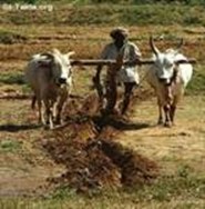
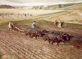
b) ANIMAL POWER: Power generated by use of oxen and buffaloes and camels involves pulling of courts and plough under the guidance of human beings. Animals used are drought animal.
LIMITATION
Farmers have to posses the drought animal.
Animal’s disease and parasite.
Vegetation availability for grazing animals.
Land topography i.e. layout of the land should be reasonable plat and with light soil.
An advision service to train and advice farmers on the use of animals and equipment.
QUALITIES OF A DROUGHT ANIMAL
They should be healthy and strong.
They should have short horns.
They should be at the age of 2-3 years.
Selection should be done in pairs.
o Similar size
o Similar strength
o Similar temperate
They should be castrated male animals.
They should have humps for a yoke.
They should be of quite temperate.
NB: Preferably nose ringed to make it easy for people to control.
HARNESSING
Meaning: Is the process of hitching implements to drought animals using a harness.
TYPES OF HARNESS
YOKE HARNESS
Commonly used in Tanzania, It consists of beam, skey, straps and U-bolt.
It is commonly short about I.5m long (Beam Length), when used in ploughing and harrowing while other operations like cultivation i.e. weeding and ridging require long beamed yoke of about I.4m. Physical structure: Is a smooth piece of wood to be rested on the neck of an animal.
Skeys: Piece of wood which are fitted into beam perforation so as to keep animals in position. U-bolt: A device fixed at all the centre of a beam where an implement can be fixed.
Straps: Leather made ropes which are lied skeys below animal neck.
COLLAR HARNESS
Collar harness is a single animal harness consisting of a collar and strips.
Methods of training animals
i. Far Eastern method (Indian type)
Requirements: Neck rope, nose rope, through nose ring, rein la rope connecting nose and neck rope used for guide animal during operation, one pair of oxen, and one person implement.
This method involves use of one pair of oxen and one person controls both oxen and implement control of animal is archived by rope passed through a hole and around the neck.
ii. Traditional method
Requirements: one or more pairs of oxen, one people, implement and other as above.
This involves two pairs of oxen guided by two people, one in front loading animals and another person at the near controlling implement.
A trained pair is in front, untrained pair is in the near. Procedure; each animal should be given a name.
Retraining an animal by rope to make him accustomed to being tied and controlled by a rope.
Animals should be fixed at a distance of about I.2m apart to make them accustomed to move on pairs.
Tying the pair with a yoke at least daily for 3-4 days to make them familiar with yoke.
Use of suitable commanding words like Go- nenda, Turn right- kata kulia.With the help of reins
Familiarize pulling by pulling a piece right log attached the yoke by means of chain.
Use the oxen for light work as a short and gradually change heavier work.
After about I0 days, harness the animal to a plough.
NB: People training oxen should be calm, patient from and consistent.
Management of oxen: It’s important so as to obtain maximum power output. This involves the followings;
Utilization of animal should be done in cooler position of the day add permitted to eat, drink and rest.
Example:
|
6:00 am release to graze and water |
4:00 pm release to graze and water
|
|
7:00 am yoke for work |
4:00 pm yoke for work |
|
10:00 am release to graze and water |
6: 00 pm release to graze and water, get them to res
|
edu.uptymez.com
Working animals should rest under shed to protect from them from wind, sun and rain
Disease and parasites such as tick borne diseases have to be controlled.
Check injures every day after work and advice possible treatment immediately.
They must be well fed on rich pasture, hay or green fodder and other recommended feeds.
Feed supplement and minerals must be fed on well cared paddock.
Tools and implements used
o -Qualities of tools and implements used: simple, strong, light, durable and inexpensive. Examples are:
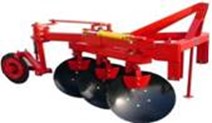
i. PLOUGH:(Both donkey and oxen)-One furrow mould board plough are commonly used made on steel and double hands and a depth wheel in front of a beam.
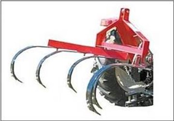
ii. CULTIVATOR: At lined implements used for inter row weeding.
iii. OX-RIDGER: An implement consisting of two mould board back to back for making ridges.
iv. CARTS: A wooden box fixed on top of two wheels connected to an axle used for transportation of inputs and products.
v. TOOLBAR: A light metal/ wooden frame to which different piece of equipment can be attached depending on the job to be done.
vi. Is supported by wheels or skids.
USE OF TRACTOR (TRACTOR POWER)
o Conversion of chemical energy of fuel to chemical power for use in the farm, petrol, diesel, coal etc is vital example of fuel used.
o Liquid fuel engine called internal combustion engines where power production is achieved through a combination of steam engines and a boiler steam generator.
Factors to consider when applying tractor mechanization
i. Farms must be large with plenty of work throughout the year.
ii. Preparation of enough capital for buying and operating a tractor.
iii. Finding skilled people/ personal for operating, repairing and maintaining a tractor
iv. Availability of spares and services at a reasonable price.
v. Justification of a tractor running costs with expected returns.
Limitations of Tractorization
o Tractors and spares (i.e. equipment/implements) are very expensive.
o It needs fuel and lubricants which increase cost.
o Tractor requires highly skilled labour for operating and maintenance.
o Economically not suitable for peasants as require large farms with plenty of work.
Importance
o Transporting for product/ produce, fertilizers, seeds and buildings.
o Opening up new land with subsequent fertilizers.
o Weeding and harvesting.
o Processing food and livestock feed by transmitting power to grinding machines through P.T.O.
CLASSES OF TRACTORS
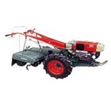
i. 2-wheeled tractor: Single axle tractor, small in size operating by individual behind it.
Used in small jobs around home e.g. garden;
ii. 4-Wheels tractor: Two axle tractor whose engine power is transmitted in both axles.
o Usually big in size depending on Hp e.g. Medium 15-16 Hp while large-75 Hp and above.
o Used in ploughing, transport etc.
iii. Track-laying tractor: With I endless tracks instead of wheels.
Commonly used:-
o Land cleaning and farming operation
o Deep tillage operations.
o Working in difficult soils e.g. swampy and soft soils.
4. WHEELED TRACTORS
Selection: Size of tractor; this depends on type and condition of soil i.e. the heavier the soil more power is required hence buying a big tractor
Type of work e.g. pulling tillage machines requires large size.
Make a model of tractor to achieve the following qualities:
i. Manufactured by reliable industry
ii. Reasonable price;
iii. Spares are easily and readily available iv) Low operational costs.
iv. Easily serviced, adjusted and repaired.
IMPLEMENTS USED BY TRACTOR
A. CULTIVATION: Include machinery used to prepare the soil for planting e.g. ploughs
o Mould board ploughs: produces more even surface so that use of harrow may not be necessary.
o Disc plough: preferred in a farm with three stumps a rotating disc roll over the obstruct instead of being caught up.
B. RIDGERS: To make ridges for crops e.g. potatoes
Disc and mould board type.
C. FERTILIZER DISTRIBUTION: To achieve even nglish-swahili/distribution” target=”_blank”>distribution of fertilizer the field.
D. PLANTERS: Implements maintained a tractor for the purpose of planting.
E. CULTIVATORS: Used as a following up after ploughs.
Disc harrows: breaking down soil humps.
a) Tined cultivators: inter row weeding.
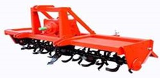
b) Rotary cultivators: a P.T.O shaft driven implement used in breaking up soil.
MAIN PARTS OF AN ENGINE
A tractor is divided into four main parts;
i. Stationary parts: these include engine block, crank case, cylinder head and oil sump. These parts do not make any kind of movement relative to their own position on the tractor.
ii. Reciprocating parts: These include pistons, inlet & outlet valves and connecting rod. The part makes to and fro movement.
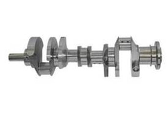
iii. Rotating parts: These include crank shaft, shaft and fly wheel.
iv. Auxiliary part: These include facilitates smooth engine function by coordinating the stationary, reciprocating and rotating parts together. They include the following systems; cooling system, fuel system, electrical system, lubricating system, transmission system and hydraulic system.
MAJOR PARTS OF THE TRACTOR
Basically the tractor can be divided into 5 major parts.
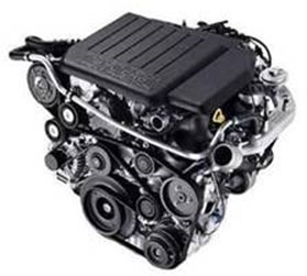
1) Engine: This is a group of parts assembled in a specific order used to convert the energy given off by burning fuel into a useful/ mechanical form.
Also may be classified according to: cylinder placement e.g. v placement, one line placement
a) Valve placement
b) Cam shaft placement
c) Cooling system – air, liquid
d) Fuel used-diesel, petrol
e) Number of cylinder
f) Principle of operation (2 or 4)
2) Clutch unit: Is a device used to connect/ disconnect the flow of power from the transmission unit.
3) Gear box: Is a system of gear which transfer and adopt the engine power to the drive wheel to advice the following: selection of speed ratio for various speeds and reverses the travel of the machine.
4) Different units: This parts do the following; transmit power to the drive excel and to allow each drive wheel to rotate at different speed.
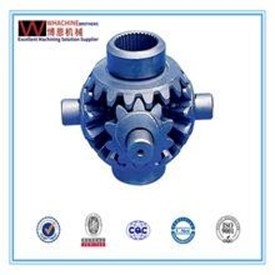
5) Final drive: This is the last phase on the power chain; it gives the final reduction in speed and increases in torque to the drive wheels.
INTERNAL COMBUSTION ENGINES
a) Stationary parts
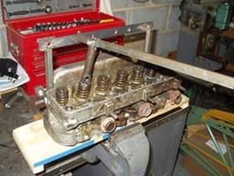
o Cylinder head: Is the cap that attaches to the top of the engine block covering the upper cylinder opens there by forming a combustion chamber in the engine between the engine block and the cylinder head there is a gasket (cylinder) which seals the engine.
o Engine block: Is a group of cylinder east in one unit usually made of cast iron, contains water jacket that surrounds the cylinder to aid in cooling.
o Cylinders: These are tubes inside the engine blocks with smooth entering finishing and serve as a guide for the pistons as they move up and down.
o Crank case: This is lower part of the block, confines the lubricating oil near the engine moving parts.
o Oil pan/ sump/ reserve: Aids the crank case in confining the oil near the engine moving parts.
b) Rotating parts:
o Crank shaft: Changes the reciprocating action of piston to rotation movement.
o Fly wheel: It is a heavy mental wheel, it attached to crankshaft and serves for purposes.
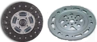
i. Smooth out engine power impulses.
ii. It can be connected to starter for starting purpose.
iii. Provide a place to mount the clutch.
iv. Provide extra turning fore
c) Reciprocating parts
Pistons: The force of exploding gases is received by the piston head and is transmitted to a piston pin, connecting rod and crank shaft.
Rings: Are fitted to the piston to seal in combustion and compression pressure as well as to prevent lubricating oil to enter the combustion chamber.
Values: Closes and opens the parts to the crankshaft so as to release air intake exhale unwanted gases.
Connecting rod: Connects the pistons to the crank shaft.
d) Engine accessories
There are components of the four separate system needed to operate an internal combustion engine, these includes; Electrical, Lubricating, fuel and cooling systems.
ENGINE CYCLES
i. Four stroke engine cycle: This involves two complete revolution of the crank shaft.
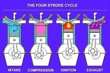
Induction stroke: As the piston moves down towards the crank case intake values open partial vacuum is created in the cylinder vaporized fuel or air moisture is forced in the cylinder.
Compression stroke: Intake values close as crank shaft rotates piston move up and compresses the fuel/air moisture.
Power stroke: The mixture burns just before piston reaches top of the travel. The expand gases which result to burning of fuel, forces the piston down to turn the crank shaft.
Exhaust stroke: As the piston goes down exhaust value open forcing burst gases out of the cylinder
ii. Two stroke engine cycle: This involves one complete revolution.
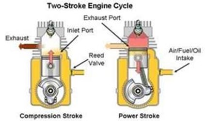
This is accomplished by eliminating the valves as used in the four strokes
In place of the valve two parts enter the cylinder wall.
|
|
PETROL |
DIESEL |
|
1 |
Light engine block |
Heavy engine block |
|
2 |
Carburetor is used |
Fuel injector pump is used |
|
3 |
Efficiency is 25-100 |
Efficiency is 40% |
|
4 |
Has spark plug |
Has no spark plug |
|
5 |
Fuel ignited by electric plug |
Fuel is ignited by compression |
|
6 |
Has a low compression |
Has a high compression |
edu.uptymez.com
ENGINE ACCESSORIES
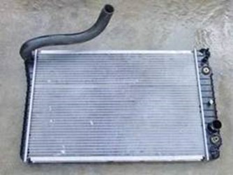
i. Cooling system: To remove unwanted excess heat.
To maintain efficient temperature under all operating condition for power, economy and minimal
Bringing the engine to operating temperature when starts up.
Components:
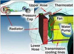
o Water cooled engine: Radiator: a device made of brass and copper to facilitate cooling and protecting it from rust and corrosion.
o The radiator consisted of a series of fine tubes with firm which provide large surface to air.
o Water is confined in tubes and is allowed to cool rapidly under the influence of air draw through the radiator by fan.
o To archive operating temperature treatment is used to limit water flow.
o Hoses: Provides connection from the radiator and water pump.
o Water pump: Circulates water through the engine.
o Thermostat: To provide constant temperature control.
Care of Radiator:-
o Keep fan and pump belts at proper tension.
o 20 mm when pressed at its middle length
o Hoses should be in good condition
o Check pressure cap for proper operation.
o Keep all connection tight.
o Keep radiator core free from insects and dirt.
ii. Fuel system: This has tank of supplying the engine with clean fuel in the correct ratio.
Diesel: Fuel is passed to injector pump, after passing, filter by gravity or pump. Fuel is then sent to injector at a very high pressure into cylinders with compressed air. When fuels come into contact with compressed air it ignites due to high temperature of the compressed air.
Petrol: After passing through filters, fuel from the tank and air is mixed at a proportional in a carburetor
1/15. In turn the mixture is sucked into the engine cylinder for combustion.
CARBURETOR: For mixing petrol and air in the right proportion.
Components:
o Fuel tanks: A fuel storage unit, situated at a position where it will not drop well protected from flying stones and busting from accident event.
o Should have a rent to allow air, to avoid vacuum creation drainage valve for cleaning.
o Fuel lines: Diesel: Low pressure fuel lines – tank- injector pump, Petrol- High pressure fuel lines – injector pump – tank.
o Fuel filter: Removes impurities from fuel.
o Fuel lift pump: Used to such, push fuel to the injector pump through filter from the tank.
o Injector pump: It times, measure, delivers fuel under pressure to the cylinders.
o Injector nozzles: Atomizes and spray fuel in the cylinders.
o Air cleaners: Prevent dust and dirt from entering the engine.
Maintenance: Check tank leak and repair, filter elements should be changed
iii. Lubrication system: This system conducts the following jobs in the engine.
o Reduce friction between moving parts.
o Absorb heat
o Seal the pistons ring.
o Cleans and flashes moving parts.
o Helps to reduce engine sound.
This is achieved by supplying a thin film of oil on the surface of moving parts.
Classes:
a) Force feed lubrication: Is a system in which oil is fed up under pressure from a pump to all bearings.
b) Splash feed lubrication: This is a commonly used in single cylinder engine where moving parts are lubricated by splashing of oil over them.
iv. Electrical system: This system involved in supplying electrical for starting engine and lubrication.
Components:
Battery: Source of electrical energy needed to operate the ignition system voltage is either 120.
Ignition switch: Used to connect and disconnect the flow of electricity across the terminals.
Resistor: Control the amount of current reading the coil.
Coil: Consists of a transformer that raises the battery voltage.
Beaker point: Connect and disconnect current flow in the circuit by opening and closing of beaker point.
Condenser: Provide a place where a primary current will flow when point are open.
v. Transmission system: A mechanical system is a common type used consisting of clutch, gear box, differential unit, final drive.
This transmits power produced by the engine to the tractor wheel as well as prouding varying speeds according to the operation being undertaken.
vi. Hydraulic system: A system consisting of oil reservoir pipeline and control valves.
Oil pumped under pressure to the cylinders canse a flow of oil to and flow the hydraulic system. This transmitting power from one point to the free linkage of a tractor used to control the setting of implements.
Also hydraulic system can be used to transfer power to external cylinder for external operations.
TRACTOR CONTROL
Some of the small important control of tractor is: starter, starter switch, clutch pedal, gear selector, accelerator pedal/ throttle, brake pedal, steering wheel, hand brake.
a) Starter switch: start the engine.
b) Clutch pedal: connects and disconnects power of the engine from the gear box for choosing appropriate gear.
c) Gear level/ selector: for selecting appropriate gear.
d) Accelerator pedal/ throttle: control speed by controlling fuel supply to the engine. e) Brake pedal: for stopping a tractor.
e) Steering wheel: control direction of movement of two tractors. g) Hand brake: safe packing of a tractor.
DAILY SERVICE AND MAINTENANCE OF THE TRACTOR
o Lubricate all grease ripples especially front wheel bearing.
o Check for oil and fuel levels.
o Check for current type pressure and battery condition.
o Check for sufficient water in radiator and top up accordingly.
o Check for excessive fuel or oil leakages.
o Check and ensure brakes are latched and nuts and bolts are tightened.
o Check and clean air cleaning system.
TILLAGE IMPLEMENTS
TILLAGE: This is a practical of modifying the state of the soil in order to provide suitable condition.
OBJECTIVES:
o Production of suitable tilt.
o Control and destruction of pest and diseases.
o Facilitate in cooperation of fertilizer and manure and weed control.
TYPES
A. PRIMARY TILLAGE: This is the initial major soil working operation designed to loosen the soil, bury plants material and residues and rearrange soil aggregates.
B. SECONDARY TILLAGE: Intended to create well retained soil condition.
IMPLEMENTS:
i. Primary tillage implements: For primary tillage.
ii. Secondary tillage implements: For secondary tillage
I. PRIMARY TILLAGE IMPLEMENTS
PLOUGHS: Ploughing is the basic tillage operation in which a layer of soil is separated from sub soil and inverted. This operation can be accomplished by disc plough, mould board plough and chisel plough.
DISC PLOUGH: An implement with concave disc mounted on bearing which rotates as they at through soil.
COMPONENTS
o Main frame: Large steel tubes to which a top link mask and cross shaft are attached.
o Standards: where disc hearings are fixed to which disc are fixed on the hub of the bearing assembly.
o Scraper: is attached to each disc and they cut the soil clothes vertically.
o Disc: for cutting and inverting the furrow slices.
NB: The orientation of the disc is determined by the disc angle and the tilt angle.
o Disc angle: is the horizontal angle between the plane of the disc face and the direction of travel.
o Tilt angle: is the angle between the disc face and the vertical axis.
When disc angle is increased the plough penetrates deeper but more power is used. The adjustment to get appropriated depth is done by adjusting the top link.
Disc plough is used in areas where mould board plough will not work satisfactory.e.g.
i. Dry land
ii. Rough and stony ground
iii. Sticky soil having hard pen i
iv. In deep ploughing.
v. Pealy and leafy mould soils where mould board plough will not turn the furrow slice.
MOULD BOARD PLOUGH: Used to give good residue coverage and soil pulveration especially in areas where soil is soft and free from roots and rocks.
COMPONENTS
o The body: used for the attachment of their tools.
o Share: makes a horizontal cut separating the further slice.
o Slade: receives the down ward pressure due to the weight.
o Land slide: counter check their side way forces.
o Disc coulter: makes the vertical out to the furrow slice.
o Skin coulter: assisting in the complete burial of crop residue and trash.
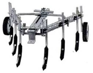
CHISEL PLOUGH:
Are used to break through the shoulders compacted on other wise impermeable soil layers to improve water penetration, best results are obtained when the soil is dry.
COMPONENTS
o Heavy duty frame: where a number of tines are bolted to it.
o Tines for opening up the soil pan.
o Shear bolt: incorporated at the foot of the line which breaks on an underground obstruction.
o Tines are arranged into 3-4 rows, depending on the type of work, soil conditions and power available.
o Rigid tines are common but spring loaded or heavy duty tines (flexible) are also available.
II. SECONDARY TILLAGE IMPLEMENT
HARROWS:
TYPES
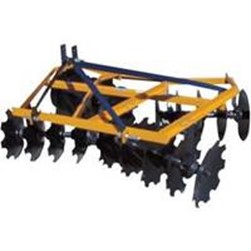
DISC HARROWS
o Offset harrow: has two gangs left and right throwing the soil on the other sides.
o Single acting disc harrow: Have two opposed gangs of disc blades throws soil out wards.
o Tundern disc harrow: has two additional gang that throw the soil backwards the centre.
ADJUSTMENT: Is done by varying the disc angle and working depth. The hand level or hydraulic vain on the harrow is used to after the cutting depth.
MAINTENANCE OF TILLAGE IMPLEMENTS
o The rotary components require daily greasing.
o Implements should be checked before starting days work.
o Loose nuts and bolts should be tightened.
o At the end of each day work, it is advisable to clean the implements.
o At the end of each season, the important must be checked for nglish-swahili/distribution” target=”_blank”>distribution and wear.
o Replacement of component sharpening or resurfacing and must proofing of the soil engaging parts should be done.
Planting equipment
o These can be hand operated equipment e.g. hoe, tractor/ animal drawn planters.
Advantages of drawn planters over hand operated planters
o Saves labor and time
o Facilitate post planting operations e.g. weeding, spraying and harvesting due to uniformly.
o Ensure uniform nglish-swahili/distribution” target=”_blank”>distribution of seeds.
o Ensure uniform planting depth.
Ways of seed planting by machine planters
a) Broad casting: This is the random scattering of seeds over the surface of the field.
BROAD CASTER: These implements distribute seeds with reasonable uniformly over a given area.
Seed covering is a separate operation or not done at all.
Demerits
Difficult to estimate the seed rate.
Other operations e.g. weeding can’t be carried out.
Seed coverage is poor. Sometimes thinning is required.
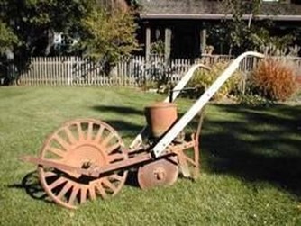
b) Row planting: Is an accurate planting pattern and covering of seeds is at about equal internal in rows.
ROWNPLANTERS: These are to distribute seeds at equal internal in
Components
o Seed and fertilizer hoppers.
o Meeting devices for seeds and fertilizer
o Delivery tubes.
o Furrow openers.
o A press wheel for covering and firming soil around the seeds.
NB: Generally the planters opens furrow and open seeds then deposits seed and fertilizer in the furrow then confirm.
o The most metering devices for most planters consists of a seed plate with a number of seed cells. The seed planter is put at the bottom of the hopper and receives its drive from ground wheel of the planter.
o The seeds are picked up in the seed cells and the plate rotates until they reach a hole at the hoppers bottom.
c) Seed drilling
SEED DRILL: This works on the same principles as a row planter. The main difference between the 2 is the metering mechanization and delivery tubes where in seed drill is placed close by Calibration of row planters
It involves: selection of a connect seed plate belt or wheel and clocking its performance.
The following steps are used to calibrate a single seed selection plate.
i. Select a suitable seed plate belt and wheel for the seed to be planted and lifted to the planter unit.
ii. Sack up the planter unit such that its device wheel rotates freely.
iii. Fill the planter unit with seeds.
iv. The device wheels is turned a number of revolutions representing a known distance which can be determined by; Distance= Number of revolutions X drive wheel circumference (cm).
v. Seeds are collected for the same number of revolutions of drive wheel in stage.
vi. Seeds are collected and counted and data obtained is used to calculate within row spacing.
Within row spacing: Distance represented by known number of revolutions o D/wheel- Number of seeds collected for the same number of revolutions of D/Wheel.
vii. Within row spacing can be raised by changing the drive sprocket ratio is step III-IV are represented until the desirable rate is obtained.
OPERATING PROCEDURES FOR PLANTING EQUIPMENT
Seed should be graded to uniform size so that they fit in the seed cell.
Set or calibrate the equipment so as to provide the required/ desired plant spacing.
Select the correct seed plate for the particular seed size.
In case of a row planter the correct spacing between rows is obtained by moving the planter unit along the tool bar.
Adjust the depth of penetration of the furrow openers.
The equipment should be operated at reasonable speed (4-10) so as not to affect the seeding rate.
For best results the field should be level free of trash and obstacles.
Greasing and oiling should be done
Clean after use.
CROP PROTECTION EQUIPMENT
The main crop protection is against weeds (herbicides) and against insect (insecticides). Types of equipment used: sprayers and dusters.
SPRAYERS
Types:
a) Syringe sprayers: This is a simple hand operated sprayer consisting of piston cylinder arranged with inlet/outlet valves.
b) Knapsack sprayers: Three types: Hydraulic, Pneumatic and Motorized.
Components
Consists of a tank strainer boom and nozzle sophisticated one have additional parts as an agitator pressure regulator and pressure gauge.
The rate of work when using a knapsack sprayer depends upon the walking speed.
Knapsack is more expensive than syringe but they are more efficient and suitable for large farms and tree crops.
c) Tractor operated sprayers (Boom sprayers)
Components are tank, pressure cylinder, pump, filter, boom, nozzles.
Tractor operated sprayers are made up of either fibre glass (strong, light, resistant but expensive) or steel tanks.
The length of the boom or sprayers bar may vary from 5-17cm.
NB: The effective working width of the boom is referred to as boom width.
Operating procedures/ precautions
o Spraying should be done when weeds/ pests are more susceptible to chemicals.
o Spraying should be avoided during rains and strong winds.
o Spraying should be done from the lee ward towards the wind ward side.
o Care should be taken to avoid inhaling the chemicals and body protection should be done.
Calibration of a tractor operated sprayers
This involves the setting up and adjusting of the sprayer in order to achieve the desires application rate. Steps
Fill in the tank with chemicals and set the pressure to the desired working pressure.
Graduated containers are used to collect resolution derived from several nozzles in a known duration.
The volume of chemicals solution collected is determined.
The application rate (l/ha) can be calculated on the basis of delivery rate, forward speed and boom width.
Application L/ha= total delivery rate L/min: – operating rate ha/min. Where: total delivery rater= volume of chemical delivery by nozzle/min. Operating rate=Area covered in one minute.
Factors affecting application rate;
i. Forward speed,
ii. nozzle size and
iii. type & ratio of water to chemical.
DUSTERS
Dusting: Is the application of powdered chemical to crops over livestock.
Dusting of crops is most effective when the leaves are dump and atmosphere is relatively dry. The operation should be avoided in the presence of strong winds.
Types
o Small hand operated: cheap effective and suitable for applying a large volume of gas at a short time.
o Machine duster: either tractor operated or aircraft operated.
o
Care and maintenance of sprayers and duster
o Clean all parts with clean water and right chemical should be used.
o Flash all parts with clean water after dusting/ spraying and flash with Na2 CO3 after using acidic chemical.
o Detach all parts and dry them up and metal parts should be treated with oil/ grease.
o Store in a cool dry and safe place. Harvesting equipments
Types
i. Manual/ hard harvesting
ii. Machine operated/ harvesting by use of combine harvester.
COMBINE HARVESTERS
o The combine harvesters outs the crop, conveys it to the threshing mechanism which sots the grains or seeds from the straw trash/chaff. The straw is left in a swath behind the combine and the chaff is brown out.
o The clean grain is elevated to the tank combines are either self propelled or tractor down.
Function compound of a combine harvester
o The reel: which is located over the cutter bar helps to pull the crops over the cutter bar.
o The screw anger: behind the cutter bar feeds the crop on the elevating mechanism to the threshing cylinder.
o The threshing unit consists of rotation cylinder and stationary concave drum between the crops which is fed.
o The high speed on the cylinder knocks the grain loose from the heads.
o The concave can be raised or lowered to adjust the gap between in and cylinder hence control the effectiveness of threshing.
o Grains remaining into the straw is carried back to the beaker which fluffs the straw so as to shake the grain out the beaker then pushes the straws into grain walker which borne the straw shaking out any remaining grain.
o Below the sleeves there is a fan which blows air upward through the sleeves lifting the material which rest on them.
o Clean grain collected is then conveyed by elevator to the grain tank.
Forage harvesting equipments
o Involves the cutting of posture grass to be fed as hay, silage or green fed. Usually the grass is out and left in the field for a few days to dry, before it is collected and stored as loose hay or balled and stored as baled hay.
o The out grass may also be collected green and to animals to direct with tools like slashes, sickle etc. even tractors. E.g: for hay making these includes mowers, swath tuners and bales, for silage making flail type harvesters are used.
MOWERS
Are two types
i. Reciprocating mowers: consists of a knife moving to and for cutting the grass with a shearing action.
ii. Rotary mowers: rotate horizontally and out the grass by impact.
o These are suitable for cutting light vegetation on fairly leveled land.
o They are stronger and better suitable to cut thick and vegetation on a rough ground.
o The cutting action of the rotary mower results into the being chopped and accelerated into pieces to which become difficult to collect the bale.
SWATH TUNERS
Grass for hay making is cut and left to dry in a swath. Also turn the swath turners.
The common type of swath turner is finger wheel swath turner / rake wheel turner.
BALERS
Are used for picking, compressing and trying to cut grass into neat bundles for easily transportation, storage and feeding, they are usually driven by P.T.O shaft.
FLAIL TYPE FORAGE HARVESTERS
Suitable for harvesting all types of green material for silage making. The flail type is cheap and simple.
It works in the same principle as the rotary mowers except that in the case the blades called flails are hinged to the vertical.
The cylinder is rotated at high speed through a P.T.O shaft.
The flails cut the vegetation on impact and flying it into a trailer.
Other source of power is wind, water, sun, nuclear, fossil fuel, charcoal, and biogas.
FARM SURVEYING AND MAPPING
Meaning: Process of observing and measuring in order to determine positions, distances, boundaries, size and elevations of various physical features of the land.
Purpose of surveying
To determine vertical and horizontal distances between two or more points on the land.
To locate physical and non physical features on the surface of the land.
To locate the direction of various features on the land.
To determine area of a given piece of land.
The process of surveying: Done in three stages
A. Reconnaissance survey: Taking a general view of the area to be surveyed so as to get overall picture of the work to be done. It is done by visual observation of the area.
B. Observing: Measuring and recording direction, angles and elevation by using surveying equipment in order to determine the relative positions and size various features of the land.
C. Presenting the data: Collected in a form which allows one to understand and interpret the information. This can be done either by: drawing, written reports, tables, any convenient form.
Basic surveying equipments
Odometer (perambulator) -Plumb bob – chain -arrows -surveyor’s rod/ leveling staff rod – tape
Plane tables – ranging pole – pre determine length of rope – range finder -plan meter
Compass – altitudes – ruler – pantograph – field note book – erasers -Sharpeners – pencil
Calculators -Abney level -Slides rulers -Hand level -Box spectant -Umbrella – Clinometers
Methods of surveying and mapping
A. LINEAR SURVEYING: This is the determination of horizontal distance between two parts. The distance can be measured pacing, odometer/ hand wheel and chaining/ taping.
i. Pacing: This is the determination of horizontal distance involving counting the number of paces/ strides made on the distance to be determined.
Advantages: The simplest method of determining distance in the field- used as a rapid means of roughly checking distance.
Disadvantage: Not so accurate as the length of a person pace depends on whether the person is walking, up or down hill or loose or firm soil in wet or dry soil and in short or tall vegetation.
NB: To improve accuracy in pacing. It is therefore necessary to determine the number of someone paces in an accurately measured 100m distance on the same ground before pacing.
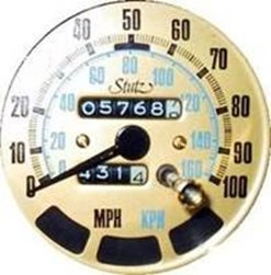
ii. Odometer/ land wheel: These are simple device which measure distance by registering the number of revolution of wheel.
Such devices may be pushed by hand or pulled by vehicle.
Odometer can be used suitable in flat smooth surface while land wheel can also be used on rough grounds.
iii. Chaining/ Taping: Instruments used by a Chains.
Types
o Gunter chain: This chain is at 66 yards land and is divided into 100 links of 7.92 long.
o Standard/ Engineers chain: Similar to Gunter chain but in this type the length of the links are 12 long. The total length is 100 feet.
o Metric chain: Usually 20-30m long with links of 20cm long.
a) Tapes: Used when greater accuracy is needed e.g. in building roads and other subsiding measurements. They are marked in hectres or centimeters of the feel or inches.
Types
o Linen tape: made of linen with steel wire woven into fibers.
o Steel tape: they are more accurate than linen.
b) Arrows: Made up of steel and is about 350cm long.
Used to mark temporary stations when surveying.
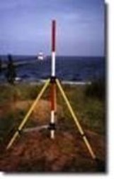
c) Ranging poles: Usually .made up of wood with a pointed at alternate bands of white and black.
Used to align survey lines on the ground.
d) Plumb bob: Used to indicate a vertical position of a point e.g. in chaining long slopes.
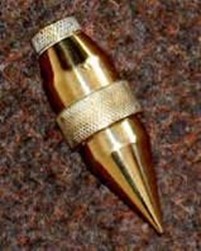
Made up of a sold piece of metal with one end pointed and a ring fixed to a flat base
e) Field note book: A book in which field notes are recorded.
B. TRIANGULATION: This is a survey method where by an area to be surveyed is divided into several triangles.
The length of side of each triangle are measured and booked.
C. LEVELING: This is a process of determining the difference in elevation between two points
Types
o Differential leveling: Involves the determination of the difference in elevation of several points apart.
o Profile leveling: This is a process of determining the elevation of a series of points at measured intervals.
Instruments/ Equipment
i. Level: There are many level types which can be selected according to the accuracy required e.g. Dumpy level, Abney level.
ii. Leveling: This is a long rod graduated in meters, lengths and hundreds of meter.
o Used together with a level to measure the size of a vertical distances above a reference plane.
D. COMPASS TRAVERSING: Is a process of determining/ establishing the positions of successive points. Types
o Closed transverse: A transverse which proceeds from one known point to another.
o Open transverse: A transverse which does not close into a known point.
SCALES AND THE CALCULATION OF AREAS
The scale of a map: This is the ratio of the plotted length on a map or plane to the actual length on ground. Used to present the generally large survey feature on a map or plan.
Ways of showing scales on a map/ plan
a) Imperial scales: This scale is represented by a length in inches on a paper and is equivalent in some other units on the ground e.g. 1 representing 1oo.
b) Metric scales: Similar to imperial scale except that the units used are metric e.g. 1cm represents 100m.
c) Natural scales: This scale is represented as a ratio can be measured/ used with any system of units of measure e.g. 1:100,000 may mean: 1cm or inches on the map represent 100,000cm or inches on the ground.
d) Scale bars: This is the method of indicating scale on the map or plan. Usually reproduce on the drawings to provide a ready means of scaling distances.
Calculation of Area
Area of land surveyed plots can be calculated by using any of the following method;
a) Dividing the map or plot into geometrical figures
Triangles (triangulation) and squares are the geometrical figures usually used for area determination. The plot is divided into triangles. The measurement are converted to actual distances using the scale of the map, the area of each triangle is the calculated by using Y to base X height formula*Total area of plot is the sum total area of triangles.
When using square method square tracing paper is placed over the plot whose area is to be determined the number of whole squares within the plot is then counted, the partially filled squares are estimated a fractions of whole squares. These are then added so as to get an appropriate number of whole squares.
The total area of the plot is equal to the sum of the squares.
b) Using ordinates by
Trapezoidal rule: Under this method the total area is equal to the common distance apart multiplied by the sum of half the first and last ordinates plus all other ordinates i.e. Total area= d (1/2O1+O2+O3+…..OR-D + ½ on).
Simpson’s rule: In this methods total area is equal to one third the common distance apart multiplied by the sum of the first and last ordinates plus twice the sum of the other add ordinates plus four times the sum of the even ordinates i.e. Total area=d/3(01+4o2+2o3+4o4+……2o(n-2)+4o(n-1)+0n)
c) Using a plan meter
A device which allows is to be mechanically obtained by reading off a graduated unit.
ERRORS
These are three kinds of errors in measurement.
i. Systematic or cumulative errors: Sources are
a. Wrong length of the tape/ chain.
b. Poor straightening of tape/ chain.
c. Poor ranging.
d. Temperature variations.
e. Slope
f. Sag
ii. Compensating / Accidental errors: Sources are
a. Variation intention of measuring tape
b. Wrong holding of tape and station marking.
iii. Gross errors: Sources are
a. Displacement of arrows/ station marks.
b. Miscounting tape/ chain lengths.
c. Misreading the tape/ chain.
d. Wrong booking of field notes.
THE PROCESS OF CHAINING
i. The head chain man with the zero and of the chain unrolls it towards the reference point. The near chain man holds the other end of the chain at the starting point.
ii. 1st 100cm measurement: The head man should have 10 pin regardless.
iii. The real man should align the head man by sighting on the reference point the chain should be straight and stretched.
iv. When the rear man has 100m mark exactly on the starting point he will call stick. The head man will place a pin.
v. The rear man pickup the pin and walks forward while the head man pulls the chain to the next point. When the end of the chain is about 6m from the pin on the ground, the rear man call chain to signal the head man to stop
vi. Procedures iii-iv are repeated until the head man had no more pins or reference point is reached rear man gives 10pins to headman.
NB: Both men should count pins. The distance to the 11th pin this is in the ground in 10 chain lengths or 1000m
o The number of pins held by the rear man in the distance from the starting point in hundreds of meters. vii) Chaining continues until the reference point is reached.
EXAMPLE OF CHAIN SURVEYING AND BOOKING
a) Method of setting off set to the chain line, off sets: line measured perpendicularly to the chain line.
1) Using an optical square
2) Using right triangle method
b) Assumption: The ABCD farm below with a fence boundary on one side; a farm house and garage. The following procedure can be used to survey the farm.
Procedure
i. Chain line AB and book the readings 10, 20, 30, 40, 50, 60, 70, 80, and 90.
ii. Take the offset of the fence which is 10m from point A and B m on the first end of hence on the chain line.
iii. Take the offset of the end of the fence which is 70m from point A and 15m from machine.
iv. Take the offset of the other end of the house which is 40m from A and 25m from chain line.
v. Book reading and repeat the procedure until all the survey lines are completed booking each line on separate pages of record sheet.
LEVELING
Differential leveling
Assumption: Finding a difference in elevation between points A & B in a farm.
Terminologies
i. Bench Mark (BM): Is a fixed point of reference for leveling, whose height above the datum is known
ii. Datum (D): Is any level surface to which elevation of points may be referred.
iii. Reduced Level (RL): Is a height or elevation behind the fore sight.
iv. Back Sight (BS): Is a height or elevation behind the foresight.
v. Fore Sight (FS): Is a height or elevation taken at succeeding stations of leveling area before shifting instrument level.
vi. Height of Instrument (HI): Is a reading taken at station added to the elevation of that point (i.e. BM+BS=HL).
a. A man reading leveling instrument.
b. N0 staff man.
vii. Intermediate Sight (IS) and Turning Point (TP) Procedure
1) The staff is held at “A” and the instrument level is set at point 1(pc).
The first reading taken at station A is a back sight (BS) say 1.5m
The reading is added to the elevation of station A to get the height of instrument (HI). i.e. 400+1.5=401.5 where 400m-BM, 1.5M-BS, 401.5m-HI.
2) The staff man moves first station P1 to station 1(S1). The instrument level is turned so that a reading is taken at station 1.This is a Fore Sight (FS) say 1.9m. The elevation of station SI, to determined y HI-FS i.e. 401.5-0.9=400.6 where401.5-HI, 0.9-FS, 400.6-Elevation
3) The level man moves to position P2 and sets the instrument to read the staff at station S1 (say 1.2m) reading s added to the elevation of station S1, to get the new HI. i.e. 400.6+1.2=401.8 where 400.6- Former HI, 1.2-BS, 4001.8-New HI of P2
4) The staff man moves to S1 and as IS reading is taken (say 1.4m). This reading is subtracted from HI to get the elevation of S2
i.e. 401.8-1.4=400.4 where 401.8=P2-P1, 1.4-FS, 400.4-Elevation of S2
5) The level man moves to position P3 from which he reads the BS from staff at position P3 from staff at position S2 ( Say S2=1.8m). This reading is added to the elevation S2 to get the new height of instrument HI i.e. 400.4+1.8=402.2 where 4042.2-P3HI, 1.2- BS 400.4- Elevation of S2
6) The staff man moves to station B and FS reading is taken (say0.2m). The reading is subtracted from HI to get elevation of point B
i.e. 402.2-0.2=402.0 where 402.2-HI of P3 0.2-FS
402.2-0-Elevation of station B
PROFILE LEVELING
Profile leveling is a process of determining the elevation of series of points at measured interval along a survey line.
Procedure
1) A benchmark is chosen where the staff will be stationed and BS reading is taken (say 6000m).
2) An instrument is placed at position PX and BS reading is taken as BS from the bench mark ( say 0.6m).
3) The staff man moves to station A and reading is taken (IS) 0.9. The elevation of point A in the determined by subtracting the reading1 from HI i.e. 600.6-0.9, where 600.6-HI(PX),0.9-IS, 599.7- Elevation of A
4) The staff man moves to S1 and 1S reading is taken (say 1.2) the elevation of S1 is then determined by subtracting IS reading from HI i.e. 600.6-1.2=599.4 where 600.6-HE(PX), 1.2-IS at S2, 599.4-Elevation of S1
5) The staff man moves to S2 and IS reading is taken (say 2.1). The elevation of S2 is then determined by subtracting IS reading from HL. i.e. 600.6-2.1=599.5 where 600.6-HI(PX), 2.1-IS at S2, 599.5-Elevation of S2
6) The staff man moves to S3 and FS1 reading is taken (say 2.9). The elevation of S3 is then determined by subtracting FS from HL i.e. 600.6-2.9=597.7 where 600.6-HI(PX), 2.9-FS at S3, 597.7-Elevation of S3
7) The level man moves to position PY and sets the level. This point is also known as Turning Point (T.P) BS reading is taken (say 0.5m). A new HI is determined by adding Back Sight to the elevation of S3 i.e. 597.7+0.5=598.2 where 597.7-Elevation of S3, 0.5-BS, 598.2-New HL
8) The staff man moves to S4 and IS reading is taken is taken (say 0.9m). The elevation of S4 is then determined by subtracting IS from the new HI i.e. 598-HL, 0.9-IS at S4, 597-Elevation of S4
9) The staff man moves to S5 and IS reading is taken (say 1.4m). The elevation of S5V is then determined by 598.2 -1.4=596.8m where 598.2-HI, 1.4-IS at S5, 596.8-Elevation of S5
10) The staff man moves to point B and a final reading (a FS) is taken which is a Fore Sight (say 2.3m). Elevation of B is determined by 598.2-2.3=595.9 598.2-HI, 2.3-FS, 595.9-Elevation of B
NB: When the level was at PX the instrument man could not read the staff beyond S3 because staff was below line of sight. This shifting of PY and successive readings of BS from S3 to be taken and FS is taken to point B. All these elevation readings are called Reduced Level (R.L)
CONTOURING
Contour: This is an imaginary line of constant on the surface of the ground.
Contour line (on a map): Is a line connecting points on the map with equal elevation on the ground. Elevation of the contour line (on a map): Is represented by a number which appear on the contour line.
Example of natural contours; Ocean/ sea lake shores and rivers
USES
Used in farmers in
1. Contour ploughing
2. Contour planting
3. Laying out terraces
4. Laying out grass strips
5. Laying out water control structures
Requirements
Instrument level (Abney level) -Level man
Staff -Staff man
Procedure
A point is selected to be located on a contour line. The level man then stands on the contour line.
The staff man moves 15-30m up and down along the approximate contour as directed by the level man.
When the level man locates the point on the line a stake is stuck by the staff man remains besides in the stake while the level man moves past him another 15-30m.
The level man sight back the staff man moving up and down the slopes until he is on contour line.
0nce established another stake is stuck and the staff man moves past the level man as before.
The process is repeated until the entire contour has been located and established.
COMPASS TRAVERSING
Traverse is a method in the field of surveying to establish control networks. It is also used in geodetic work. Traverse networks involved placing the survey stations along a line or path of travel, and then using the previously surveyed points as a base for observing the next point. Traverse networks have many advantages of other systems, including:
o Less reconnaissance and organization needed
o While in other systems, which may require the survey to be performed along a rigid polygon shape, the traverse can change to any shape and thus can accommodate a great deal of different terrains
o Only a few observations need to be taken at each station, whereas in other survey networks a great deal of angular and linear observations needs to be made and considered
o Traverse networks are free of the strength of figure considerations that happen in triangular systems
o Scale error does not add up as the traverse as performed.
Azimuth swing errors can also be reduced by increasing the distance between stations
o Link traverse
o Polygonal/Loop traverse
o Open/Free traverse
o Close traverse
o Close traverse is useful in marking the boundaries of wood or lakes.
o Open survey is utilized in plotting a strip of land which can then be used to plan a route in road construction.
Surveying by open
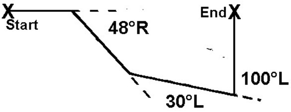
Traverse: Is a series of points on surveying lines connected established positions. Requirements: Chain/ tape, arrows, ranging poles and prismatic compass.
Procedure: The position of point A and distance and bearing from another point B is taken.
SOIL AND WATER CONSERVATION
Reasons for studying soil and water conservation factors relating to
i. Poor rain fall nglish-swahili/distribution” target=”_blank”>distribution -Excessive movement of soil
ii. Too much or too little rainfall -Moisture retaination -Control of excess water
iii. Low soil fertility due to poor soil structure and absence of essential nutrients.
SOIL CONSERVATION: This refers to all practices which are geared at preventing excessive movement of soil, so as to control the soil properties e.g. fertility in terms of essential nutrients supply.
WATER CONSERVATION: This refers to all practices geared at retaining the needed soil moisture and controlling excess water, so as to make effective use of too much or too little or poorly distributed rainfall.
SOIL CONSERVATION
SOIL EROSION: This is the wearing and removal of soil particles by action of WATER and WIND
EFFECT OF SOIL EROSION
i. Reduces the productivity of land due to decline of soil fertility.
ii. Render large tracts of land unable due to gullies.
iii. Causes silting of dams and rivers.
iv. Decrease in amount of water available for crop growth due to excessive runoff instead of percolating in soil.
v. Ennglish-swahili/courage” target=”_blank”>courage floods due to sitting of rivers and dams destroying agriculture land, crops and properties.
SIGN OF SOIL EROSION
i. Appearance of gullies
ii. Appearance of muddy rivers and streams
iii. Sitting up of dams and water ways
iv. Appearance of bare soil.
CAUSES OF SOIL EROSION
i. Deforestation: This is the cutting of trees indimiscriminately without replanting.
ii. Overgrazing: This is continuous grazing or animal over a certain piece or land causing the following:
o Weakening of the plant root system binding the soil due to the removal of the grass cover.
o Trampling of the soil by the animals.
iii. Bad farming practice: This includes such practices as:
o Planting animal crop on steep slopes
o Clean weeding of plantation crops.
o Uncontrolled burning of the bush.
o Ploughing along the slopes
iv. Destruction of vegetation along the river banks: Through destruction of trees and grass, which hold together the soil along the bank and thus loosening the soil.
v. Living organisms: They loosen the soil hence more susceptible to erosive agents.
AGENTS OF SOIL EROSION
i. In high rainfall areas WATER is main agent
ii. In dry areas with sand soil WIND is main agent.
WATER EROSION
FORMS:
Sheet erosion: This is a uniform removal of soil from wide area
Rill erosion: Is the removal of soil where by small channels (rills) are formed.
Gully erosion: Is the removal of soil through well developed deep channels called gullies.
WIND EROSION
FORMS:
Saltation: This is the suspension of soil particles in the air and skipping and bouncing of soil particle on surface.
Surface creep: This is the rolling/skidding of soil particles in continuous contact with the soil surface.
EXAMPLE OF SOIL AND WATER CONSERVATION SCHEMES IN TANZANIA
A. HASHI-HIFADHI ARDHI SHINYANGA
B. HESAWA- LAKE ZONE CONSERVATION SCHEME
C. HADO- HIFADHI ARDHI DODOMA
D. KAEMP- KAGERA CONSERVATION SCHEME
E. LOWER MOSHI IRRIGATION SCHEME- KILIMANJARO
F. RUBADA- RUFIJI BASIN DEVELOPMENT ASSOCIATION
G. KIHANSI CONSERVATION SCHEME- MTERA
H. MALDO IRRIGATION SCHEMES METHODS OF SOIL EROSION CONTROL
Goal: Regulation of movement of water and wind on the surface of the soil which is achieved by;
i) Mechanical measures ii) Agronomic measures
A. MECHANICAL MEASURES
Refers to all measures that will break up the slop and intercept the run of water before its volume and velocity can cause erosion, Therefore it involves mainly construction of different structure such as:
a) Hill side ditches: These are small ditches made with a gradient of a half to one percent, with the earth removed from the ditch and placed on the lower side to form a ridge.
These are normally 3cm deep spaced 20m-30m apart along the contour.
b) Terraces: This involves the construction of small walls of stones or earth, rain forced with vegetation to form barrier against the movement of soil, these are of three types
i. Narrow based terrace: These are narrow banks kept wide permanent grass spaced between 15m-30m apart with slope of about 6%
ii. Broad based terrace: A wide banked terrace used in slope of 2-4% spaced about 30m apart. iii) Bench terrace: This involves reshaping the land into a series of steps spaced 7.5m apart.
The steeper part must be kept (bench face) under permanent grass or protected by stones.
The procedure is a big large ditch on the contour and to throw all the soil on the upper side to form a ridge on which grass is granted.
c) Storm drains or diversion ditches: These are channels constructed around the slope in the upper most part given a slight gradient to cause water to flow to the desired outlet. The design and capacity of the ditch will vary according to the type of soil, slope and estimated peak runoff which may occur in the area.
B. AGRONOMIC MEASURES
Refers to specific farming practices which can be used to reduce the severity of water and wind erosion. These include;
a) Minimum tillage: This is a minimum disturbance of soil involving as little cultivation as possible.
b) Contour strip cropping: This is a practice of growing crops which give little soil cover e.g. maize in alternate strips with dense crops (e.g. cassava) along the contour line or is a practice of growing alternate strips of different crops in the same field along a contour.
c) Vegetative buffer crops: This is a practice of leaving strips of uncultivated land between strips of cultivated land which acts as barriers
d) Mulching/ Use of cover crops: Mulching is a practice of cover the soil surface with straws, cut herbage or leaves so as to protect the soil from direct rain drops, wind and sun’s heal as well as retaining soil moisture in areas with limited moisture supply. When it decomposes it adds organic material in the soil.
e) Wind breakers: Are trees/ shrubs which are grown in the direction of wind so as to reduce its velocity.
f) Reforestation: This is the practice of growing trees in bare land. This protects soil and crops and the roots bind soil. Others:
Avoiding indiscriminately slashing and burning.
Avoiding deforestation.
Avoid over grazing.
Avoid cultivation on very steep slopes.